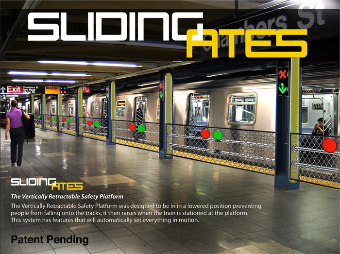
This disclosure relates to retractable platforms and more particularly, to a retractable safety platform system for providing a physical barricade platform along with audio and visual warning messages at a station platform so that a passenger will not fall or be pushed onto a path of an oncoming train.
I am the inventor of the patented subject matter claimed in U.S.Patent No.8,020,496 (“496 patent”) derived from U.S. patent application 12/381,828, filed March 17,2009 now abandoned, which claims the benefit of provisional application 61/069624, filed March 17,2008 now abandoned.The claimed subject matter of the present application covers patentable modifications to the claimed subject matter of the “496 patent”. The file wrapper of the “496 patent- and associated patent application(s) referenced above- are incorporated herein by referenced to their entireties.
America in the 21st century is a nation of commuters. Most of us work someplace outside the home, and for most of us, that place lies somewhere down the highway. For commuters who live in the suburbs or, increasingly, the farther removed “exurbs,” the commute can be extreme. It is not uncommon for a person employed in San Francisco to live in Modesto or Gilroy, and drive several hours twice a day; and similarly highway-bound existences can be found on the ever-receding peripheries of any major city. Still, with all the news about road-rage, traffic jams and the mounting hassels of commuter lifestyle, we may forget that millions of Americans commute in an other manner — by
trains. Trains offer certain advantages when it comes to the morning and evening commute.
For one thing, it’s entirely possible to read the newspaper on the on the morning train and take a nap on the evening commute. The countryside reels past, the click of the wheels on the tracks instills a reassuring rhythm in the mind and body, and the train proceeds (on most days) like clockwork, traveling down its accustomed track by predestination. On a commuter train, one can relax and prepare for –or forget, once they’ve been met– the demands of the business day. the commuter brethren on the highway, meanwhile, are engaged in a heartpounding, high stakes
game that is equal parts patience and aggression; small wonder that they come home exhausted and irritable, hands shaking untill the first cocktail is down. Given the choice, what veteran of the highway commute would not prefer the train?
Then again, commuting by train or subway does have its downside. For one thing, the train commuter must navigate among a sea of strangers each morning and evening, generally at times when he or she most craves silence or solitude. For subway commuters, this lack of privacy and personal space is extreme, as one is frequently shoulder-to-shoulder, standing in a closely packed crowd of fellow riders. On trains, one’s seatmate is often a stranger, and not always a polite or agreeable one.
And then there is a rush out the doors when the train reaches the patform or station “people pushing, people shoving” as one as one rock-n-roll song put it, “on the 8:15 into the city.” On top of all this, there is the very real hazard involved in actually stepping off the train and onto the platform. You have to consciously step out, or risk falling between the train and the concrete–a mistake that could be the ruin of your day, certainly, if not your life. In the hurly burly of the commute, people do in fact fall and get injured between trains and platforms, a problem that the present disclosure will solve.
Platform gaps, up to 15 inches wide, can be caused by a station’s curvature and the design of the trains, whose sides are straight. Fliers, posters and yellow stickers on the train doors urge riders to “Watch the Gap.” Subway and commuter train stations are busy, crowded places where large groups of people are constantly in motion, and frequently in motions opposed to one another. Scrambling to get aboard a train or attempting to get off at the station, a passenger frequently finds himself or herself in an anxious, distracted state of mind — a state
more likely to lead to a potentially catastrophic misstep.
Accordingly, the present disclosure is disclosed in order to overcome the above noted shortcomings. The vertically retractable platform system is convenient and easy to use, lightweight yet durable in design, and designed to be a physical barricade platform along with audio and visual warning messages at a station platform so that a passenger will not fall or be pushed onto the path of an oncoming train.
BRIEF SUMMARY OF THE DISCLOSURE
In view of the foregoing background it is therefore an object of the present disclosure to provide a retractable barricade platform system including a physical barricade platform along with audio and visual warning messages at a station platform so that a passenger will not fall or be pushed onto a path of an oncoming train. These and other objects, features, and advantages of the disclosure are provided by a retractable safety platform system for use between a train and a station platform thereby ensuring a passenger will not fall or be pushed onto a path of a train.
Such a retractable safety platform system includes a rigid barricade platform adapted to be anchored to an outwardly facing side of the station platform registered along a vertical plane, and a mechanism for automatically reciprocating the barricade platform along a vertical linear travel path upon detecting first and second triggering events respectively. Notably, the linear travel path is defined along the vertical plane extending above and below a top surface of the station platform. In this manner, the barricade patform is displaced from a lowered retracted
position to a raised extended position when the first triggering event is detected. Likewise, the barricade platform is displaced from the raised extended position to the lowered retracted position when the second triggering event is detected.
In a non- limiting exemplary embodiment, a plurality of light sources are attached to an inwardly facing side of the barricade platform. Such light sources are selectively illuminated between active and inactive modes when the first triggering event and second trigger event are detected, respectively.
In a non-limiting exemplary embodiment, such illuminable light sources include, for example, warning lights. In addition emergency stop sensors (similar to an elevator door), rubberized bottom cushions and an audio warning system may be employed by the light sources. For example, audible messages are replayed to remind passengers to stand away from the outwardly facing side of the barricade platform before the barricade platform is vertically raised (closed) and lowered (opened). Thus, the subject matter of the disclosure creates both audio and visual messages with a physical barricade platform at the station platform so that no one will fall or be pushed onto the path of an oncoming train. The vertical displacement of a barricade platform allows connection to the barrcade platform and stops people from falling or being pushed onto train tracks. The barricade platform also has sensors to automatically stop and/or reverse directions in case someone or something is obstructing its vertical travel path. Thus, the controller automatically learns when it is safe to vertically raise and lower the barricade platform a the train approaches and departs. Of course, a manual override switch is provided a well.
In a non-limiting exemplary embodiment, the automatic barricade platform reciprocating mechanism preferably includes a power-actuated drive mechanism centrally engaged to a bottom surface of the barricade platform wherein the drive mechanism is adapted to be conneceted to the outwardly facing side of the station platform, a controller including a processor and a memory communicatively coupled thereto, a plurality of sensors located at the barricade platform and being communicatively coupled to the controller respectively, and a light switch communicatively coupled to the controller and the light sources. In this manner, the controller causes the drive to toggle between alternate operating modes upon detecting the first and second triggering respectively. Furthermore, the controller causes the light switch to toggle between closed and opened positions uopon detecting the first and second triggering events respectively.
In a non-limiting exemplary embodiment, the memory includes programmable software instructions that cause the controller to verify an authenticity of the first and second triggering events.
In a non-limiting exemplary embodiment, a first group of sensors generates and transmits true first output signals upon detecting the first triggering event respectively. A second group of the sensors generating and transmitting true second output signals upon detecting the second triggering event respectively. In this manner, the first and second sensor groups generate and transmit respective first and second false output signals when the first and second triggering events are not detected.
In a non-limiting exemplary embodiment, the controller is responsive to the first and second output signals and thereby generates and transmits first and second control signals respectively. Notably, upon receving the first and second control signals, the drive mechanism is caused to rotate in clockwise and counter clockwise directions respectively. Furthermore, upon receiving the true first and second output signals, the controller further generates and transmits third and fourth control signals to the light switch thereby toggling the light switch between the closed position and the open position respectively. In this manner, the light soures are activated and deactivated when the light switch is at the closed position and open position, respectively.
In a non-limiting exemplary embodiment, the drive mechanism includes a rotary motor adapted to be coupled to an existing power source locted at the barricade platform, and a plurality of rectilinear drive shafts directly coupled to the rotary motor respectively wherein each of the drive shafts is coupled to the rotary motor and oppositly extends away therefrom respectively. Notably, the drive shafts are registered along a linear axis oriented parallel to a rear edge of the barricade platform.
In a non-limiting exemplary embodiment, the drive mechanism further includes a driven shaft spaced from the drive shafts and registered parallel thereto, a plurality of primary cogwheels anchored to respective distal ends of the drive shafts wherein each of the primary cogwheels is synchronously rotated with the drive shafts as the motor rotates in the clockwise and counter clockwise directions. A plurality of secondary cogwheels are anchored to distal ends of the driven shaft wherein each of the secondary cogwheels is synchronously rotated with the driven shaft as the motor rotates in the clockwise and counter clockwise directions.
In a non-limiting exemplary embodiment, the drive mechanism further includes a plurality of primary serrated tracks statically connected directly to the bottom surface of the barricade platform wherein the primary serrated tracks are configured in such a manner that the primary cogwheels remain continuously and directly engaged with the primary serrated tracks during the reciprocating motions. A plurality of secondary serrated tracks statically connected directly to the bottom surface of the barricade platform wherein the secondary cogwheels remain continuously and directly engaged with the secondary serrated tracks during the reciprocating motions.
In a non-limiting exemplary embodiment, the barricade platform is caused to linearly reciprocate along the vertical plane as the drive shafts, the driven shafts, the primary cogwheels and the secondary cogwheels rotate along the clockwise and counter clockwise directions respectively.
In a non-limiting exemplary embodiment, the automatic barricade platform reciprocating means further includes a plurality of primary protective guide rails situated at opposed lateral ends of the barricade platform respectivly, wherein such primary protective guide rails are anchored to the outwardly facing side of the station platform. A plurality of secondary protective guide rails situated at opposed lateral ends of the barricade platform respectively, wherein such secondary protective guide rails being anchored to the outwardly facing side of the sation platform. A plurality of primary guide wheels rotatably attached within each of the primary protective guide rails, wherein the primary guide wheels are configured in such a manner that the barricade platform remains intercalated between anterior and posterior rows of the primary protective guide rails while reciprocating between the retracted and extended positions respectively. A plurality of secondary guide wheels are rotatably attached within each of the secondary protective guide rails,wherein the secondary guide wheels are configured in such a manner that the barricade platform remains intercalated between anterior and posterior rows of the secondary protective guide rails while recipprocating between the retracted and fully extended positions respectively.
In a non-limiting exemplary embodiment, each of the primary protective guide rails and the secondary protective guide rails has a longitudinal length registered parallel to the linear travel path of the barricade platform for maintining the barricade platform at a substantiably stable position during repeated reciprocating movement.
For any hurried commuter-and especially for those elderly or mobility-restricted commuters for whom these transitions are a particular obstacle-the retractable safety platform system provides a convenient, reliable barrier between the train and station platform.
The present disclosure further includes a mehtod of utilizing a retractable barricade platform system between a train and a station platform thereby ensuring a passenger will not fall or be pushed onto a path of the train. Such a method includes the steps of: providing and anchoring a rigid barricade platform to an outwardly facing side of the station platform registered along a vertical plane; and providing a mechanism for automatically reciprocating the barricade platform along a vertical linear travel path upon detecting first and second triggering events respectively, wherein the linear travel path is defined along the vertical plane extending above and below a top surface of station platform.
The method further includes the steps of: when the first triggering event is detected, displacing the barricade platform from a lowered retracted position to a raised extended position; and when the second triggering event is detected, displacing jthe barricade platform from the raised extended osition to the lowered retracted position. there has thus been outlined, rather broadly, the more important fetures of the disclosure in order that the detailed description thereof that follows may be better understood, and in order that the present contribution to the art may be better appreciated. There are additional features of the disclosure that will be described hereinafter and which will form the subject matter of the claims appended hereto.
It is noted the purpose of the foregoing abstract is to enable the U.S. Patent and Trademark Office and the public generally, especially the scientists, engineers and practioners in the art who are not familiar with patent or legal terms or phraseology, to determine quickly from a cursery inspection the nature and essence of the technical disclosure of the application. The abstract is neither intended to define the disclosure of the application, which is measured by the claims, nor is it intended to be limiting as to the scope of the disclosure in any way.
BRIEF DESCRIPTION OF THE SEVERAL VIEWS OF THE DRAWINGS
The novel features believed to be characteristic of this disclosure are set forth with particularity in the appended claims. The disclosure itself, however, both as to its organization and method of operation, together with further objects and advantages thereof, may best be understood by reference to the following description taken in connection with the accompanying drawings in which:
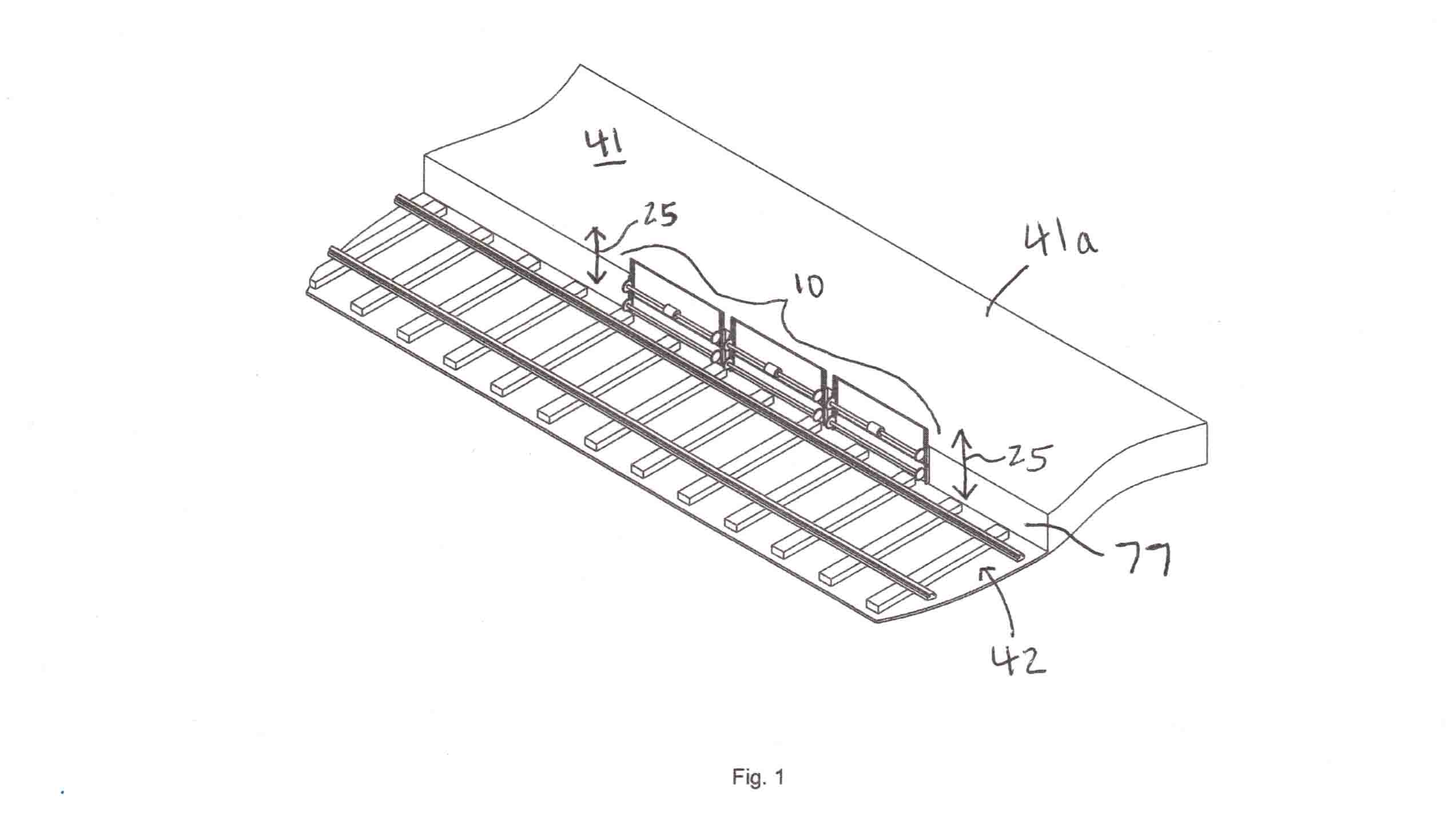
FIG.1 is a perspective view showing an exemplary environment at which an automated retractable safety platform system is employed, in accordance with an embodiment of the present disclosure;
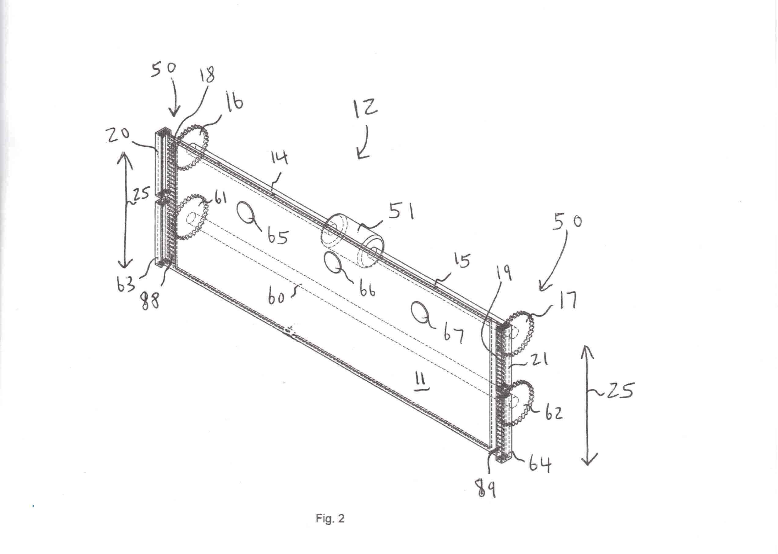
FIG.2 is a perspective view showing a barricade platform operably supported by an automated barricade platform reciprocating mechanism;
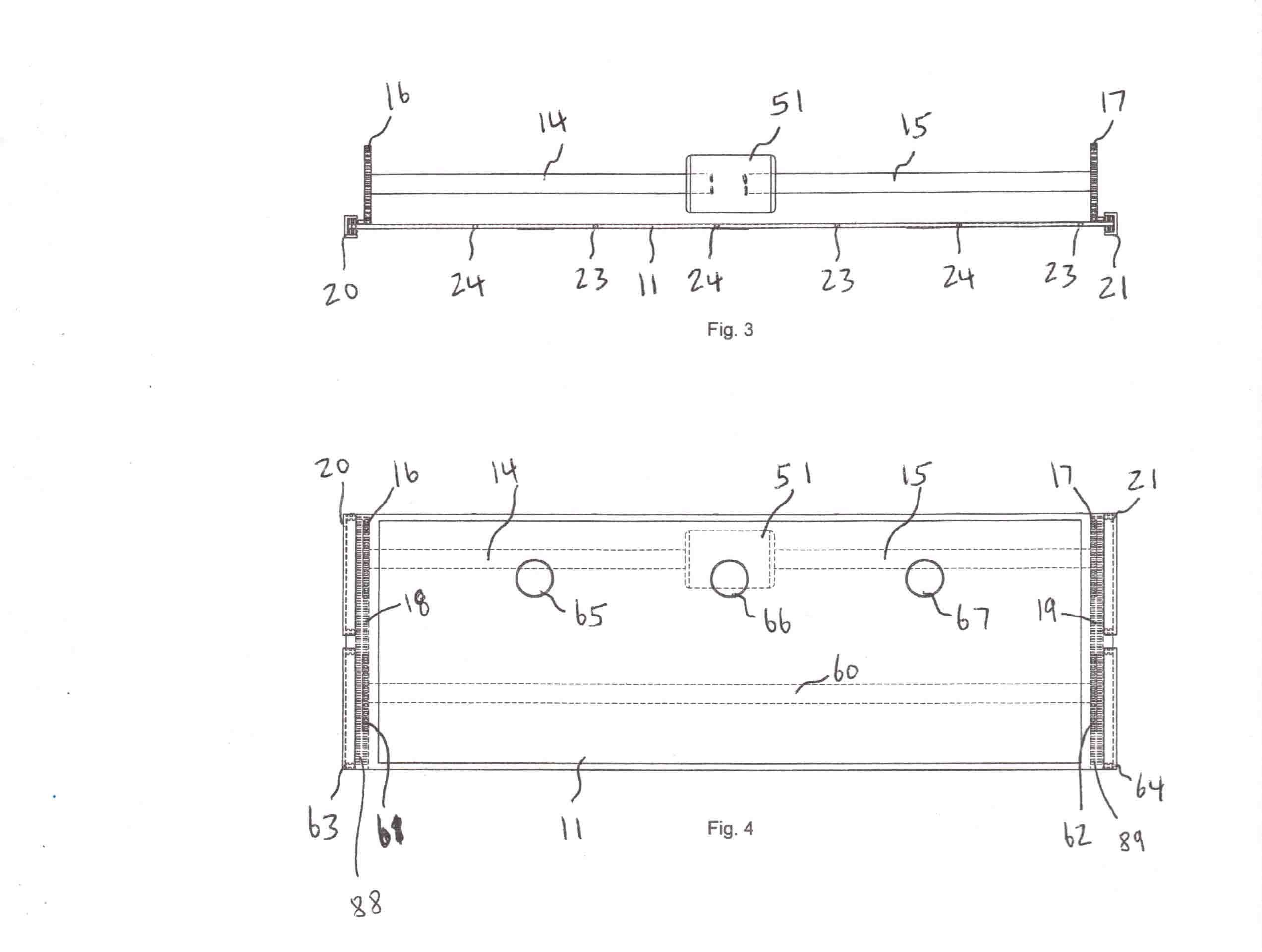
FIGS.3 and 4 are top and front elevational views of the barricade platform cooperating with the automated barricade platform reciprocating mechanism and drive mechanism shown in FIG.2;
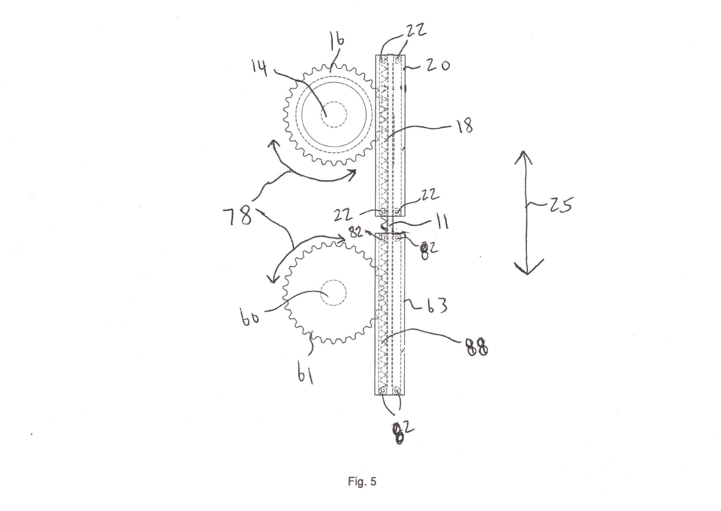
FIG.4 is an enlarged side elevational view showing one of primary and secondary cogwheels in communication with an associated one of primary and secondary serrated tracks;
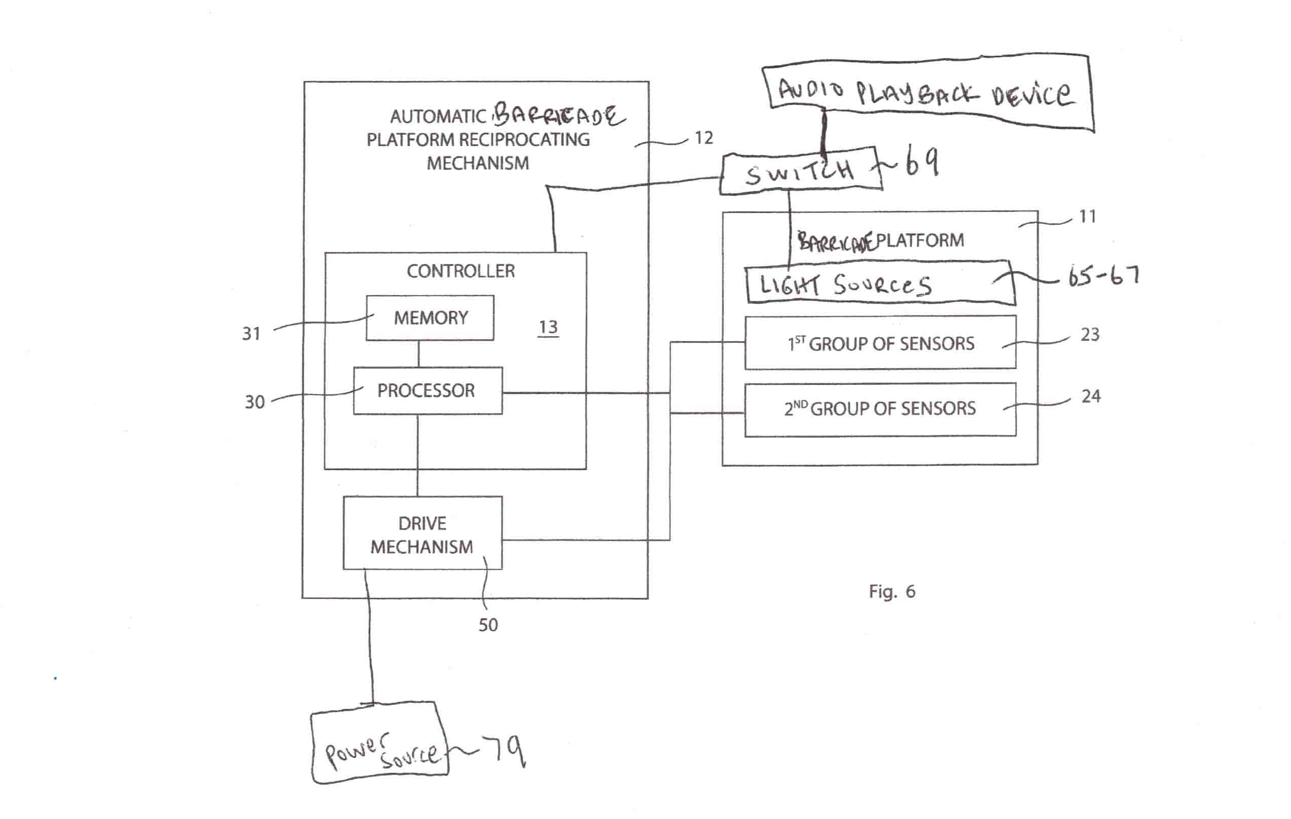
FIG.5 is a high level schematic block diagram showing the interrelationship between the major electronic components of the present disclosure.
Those skiled in the art will apprciate that the figures are not intended to be drawn to any particular scale; nor are the figures intended to illustrate every embodiment of the disclosure. The disclosure is not limited to the exemplary embodiements depicted in the figures, or the shapes, relative sizes or proportions shown in the figures.